555 Timer Schematic Symbol : 555 Timer Ic Working Principle Block Diagram Circuit Schematics : The schematic symbol for the 555 timer ic is not drawn to the layout of the physical 555 ic.
555 Timer Schematic Symbol : 555 Timer Ic Working Principle Block Diagram Circuit Schematics : The schematic symbol for the 555 timer ic is not drawn to the layout of the physical 555 ic.. V = ir, i = v/r substituting either one in the p=iv gives. Awesome 555 timer ic projects · 1. Under the library manager\component tab, select wizard and create a component by assigning the schematic symbol and pcb symbol in the dialog with the pin assignment and click the finish button. There are a lot of projects out there using the 555. Being an integral part of electronics project, 555 timer ic is very often used in simple to complex electronics projects.
1 ohm is equal to one volt/ampere. The 555 timer is one of the most iconic and popular integrated circuits of all time. When drawing a circuit diagram, always draw the 555 as a building block, as shown below with the pins in the following locations. Awesome 555 timer ic projects · 1. The pin diagram of a 555 timer ic is shown in the following figure −.
Schematic Circuit Diagram Sequential Switching Circuit Using 555 Timer Proteus Simulation from circuit-diagramz.com The schematic symbol for the 555 timer ic is not drawn to the layout of the physical 555 ic. Camenzind for the signetics corporation. It does not have pins 1 to 4 on one side and pins 5 to 8 on the other. It monitors the charging of the timing capacitor in astable and monostable circuits. V = ir, i = v/r substituting either one in the p=iv gives. The pin configuration is shown in the figures. Given the popularity of the 555 timer, i thought it. List of simple 555 timer circuits and projects · super sensitive intruder alarm:
Derivatives provide two ( 556) or four ( 558) timing circuits in one package.
If a 10uf timing capacitor is used, calculate the value of the resistor required to produce a minimum output time delay of 500ms. These on off intervals can be adjusted by varying the 555 timer output and number of counter outputs. The standard 555 timer ic is made of 2 diodes. The ohm is the symbol of electrical resistance ω. There is no 555 timer though, so let's create our own. The.asc file is the schematic. Given the popularity of the 555 timer, i thought it. Ne555p by texas instruments has a low design risk score of 0.39. The 555 timer ic is an integrated circuit (chip) used in a variety of timer, delay, pulse generation, and oscillator applications. This circuit uses very basic components like 555 timer and 4017 counter. In this video we look at a simple 555 astable circuit. Pin configuration of the 555 timer here is the identification for each pin: The use of each pin in the ic is explained below.
Its name is derived from three 5k ohm resistors ,connected in series used in it.the timer ic can produce 555 timer was first introduced by signetics corporation in 1971 as. The circuit diagrams on this website show a 555, but they could all be adapted to use one half of a 556. When drawing a circuit diagram, always draw the 555 as a building block, as shown below with the pins in the following locations. There are a lot of projects out there using the 555. In monostable mode, the duration for which the pin 3 would remain high, is given by the below formulae:
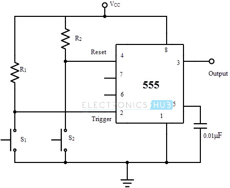
Bistable Multivibrator Using 555 Timer from www.electronicshub.org In monostable mode, the duration for which the pin 3 would remain high, is given by the below formulae: There are a lot of projects out there using the 555. Given the popularity of the 555 timer, i thought it. Pin configuration of the 555 timer here is the identification for each pin: Also, 555 timer is used to generate an oscillating pulse. The second image is the schematic symbol of the 555 timer used in diagrams: To make the 555 timer circuit you will also need several other components. The use of each pin in the ic is explained below.
This 555 timer ic can be operated with a dc supply of +5v to +18v.
Awesome 555 timer ic projects · 1. This makes it easier to read the schematic diagram. The schematic symbol for the 555 timer ic is not drawn to the layout of the physical 555 ic. Voltage doubler circuit using 555 timer ic. Pin configuration of the 555 timer here is the identification for each pin: The.asc file is the schematic. 1 ohm is equal to one volt/ampere. This circuit shows an intruder alarm using 555. The circuit symbol for a 555 (and 556) is a box with the pins arranged to suit the circuit diagram: In this project, we are using 555 timer ic to create various timer circuit like 1 min timer circuit, 5 min timer circuit, 10 min timer circuit, and 15 min timer circuit. Adjustable on off timer(using 555 astable mode) in this circuit a timer with cyclic on off operations is designed. To make the 555 timer circuit you will also need several other components. The circuit symbol for a 555 (and 556) is a box with the pins arranged to suit the circuit diagram:
Being an integral part of electronics project, 555 timer ic is very often used in simple to complex electronics projects. When drawing a circuit diagram, always draw the 555 as a building block, as shown below with the pins in the following locations. With this information you will learn how how the 555 works and will have the experience to build some of the circuits below. The.asc file is the schematic. If a 10uf timing capacitor is used, calculate the value of the resistor required to produce a minimum output time delay of 500ms.
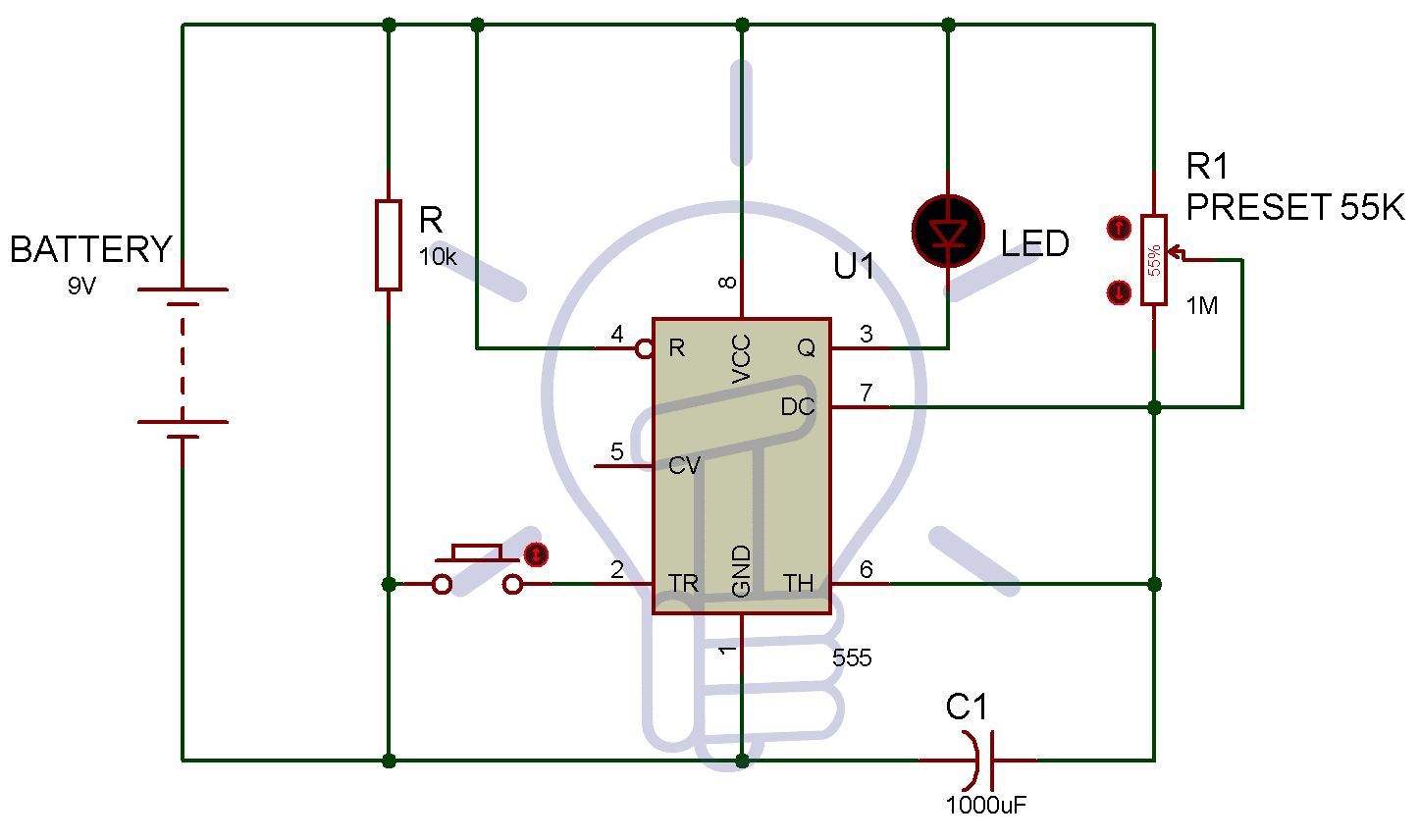
1 To 15 Minute Timer Circuit Diagram Working And Applications from www.electricaltechnology.org Between the positive supply voltage v cc and the ground gnd is a voltage divider consisting of three identical resistors, which create two reference voltages at 1 ⁄ 3 v cc and 2. A monostable 555 timer is required to produce a time delay within a circuit. Designed by analog ic wizard hans camenzind in 1970, the 555 has been called one of the greatest chips of all time with whole books devoted to 555 timer circuits. A voltage doubler circuit is a type of electronic circuit that charges capacitors through input voltage and switches these charges twice of the voltage is produced at the output as at its input. Derivatives provide two ( 556) or four ( 558) timing circuits in one package. Also, 555 timer is used to generate an oscillating pulse. The 555 timer is one of the most iconic and popular integrated circuits of all time. The circuit symbol for a 555 (and 556) is a box with the pins arranged to suit the circuit diagram:
This circuit shows an intruder alarm using 555.
However, the .lib ne555.sub statement will be needed on the schematic where the symbol is used. Now both can be associated to define a component. The circuit symbol for a 555 (and 556) is a box with the pins arranged to suit the circuit diagram: In monostable mode, the duration for which the pin 3 would remain high, is given by the below formulae: List of simple 555 timer circuits and projects · super sensitive intruder alarm: Now the schematic symbol and pcb symbol are created for the 555 timer. To make the 555 timer circuit you will also need several other components. The.plt file is the saved plot configuration file. 555 timer schematic symbol : 500ms is the same as saying 0.5s so by rearranging the formula above, we get the calculated value for the resistor, r as: The pin configuration is shown in the figures. The diagram below shows the actual pin arrangement of the 555 timer with the internal schematic diagram of the ic: This makes it easier to read the schematic diagram.

Post a Comment